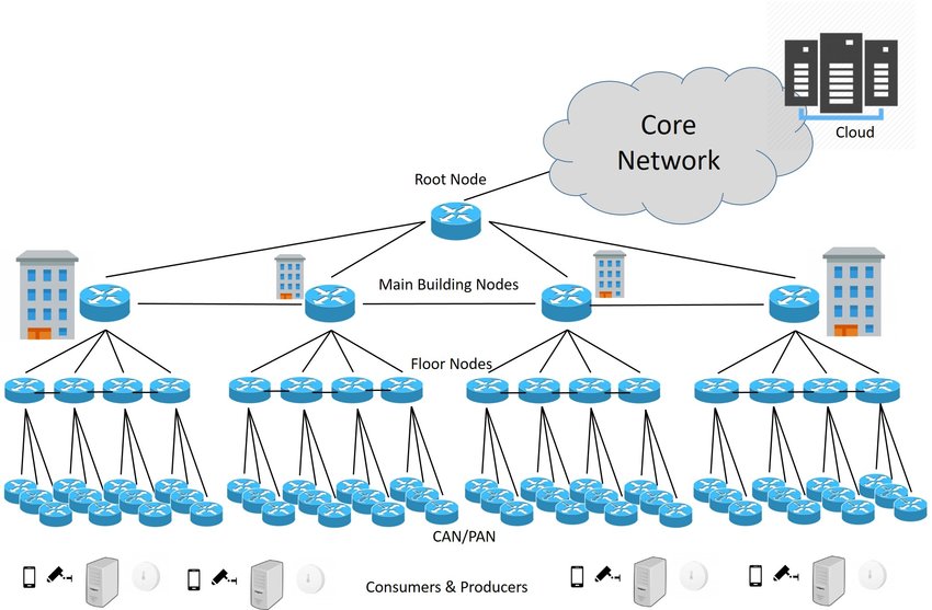
20+ cloud topology diagram
Configuration options range from selecting specific CPU models to excluding certain CPU features. Detail on versions of Horizon.

Vxlan Design With Cisco Nexus 9300 Platform Switches Cisco Nexus Cisco Ccna
Tile-Based Architecture Delivering up to 20 Million Polygons per Second.

. Added Integration with Horizon Cloud Control Plane Service. Network topology is the topological structure of a. Login with a Cisco ID.
300 in free credits and 20 free products. Network topology can be used to define or describe the arrangement of various types of telecommunication networks including command and control radio networks industrial fieldbusses and computer networks. In applied mathematics topological based data analysis TDA is an approach to the analysis of datasets using techniques from topologyExtraction of information from datasets that are high-dimensional incomplete and noisy is generally challenging.
BGP is configured between the on-premises router and a Cloud Router in the VPC network as shown in the following diagram. The following topology diagrams show example Partner Interconnect connections for Layer 2 and Layer 3. Predefined CPU models are listed in files in the directory usrsharelibvirtcpu_map.
Connections between nodes can be made with cables wires etc. This quickstart shows you how to easily install a Kubernetes cluster on AWS. This HDFS Architecture Explanation also helped in my recent interview of Hadoop Architect.
TDA provides a general framework to analyze such data in a manner that is insensitive to the particular metric chosen and provides. Describes how computers communicate internally the data flowing between them in the network and the path it takes. Everything runs in Auto-Scaling Groups Multiple OS support Debian Ubuntu 1604 supported CentOS RHEL Amazon Linux and CoreOS - see.
Explore reference architectures diagrams tutorials and best practices about Google. The following diagram shows an example of the resulting hub-and-spoke network. Then you will have to click on the category that mentions the process flow diagram so that you can start with your work.
Depending on its scope and purpose a network diagram may contain lots of detail or just provide a broad overview. It is done through the cloud or virtual resources. It has a 23 share of the cloud market and is second only to Amazon Web.
Types of Network Topology. Universal Scalable Shader Engine USSE is a Multithreaded Engine Incorporating Pixel and Vertex Shader Functionality. An alternative topology for DDR layout and routing is the double-T topology.
Network topology is the arrangement of the elements links nodes etc of a communication network. It uses a tool called kops. It generates a diagram that shows the selected components and the links between them.
Kops is an automated provisioning system. If Cloud Routers in the same region receive the same. Well explained HDFS Architecture.
Each branch could split again to support 2 chips each for a total of 4. Advanced Shader Feature Set in Excess of Microsoft VS30 PS30 and OGL20. In this topology the differential clock command and address fanout from the memory controller all branch into a T-section which can support 2 chips.
Fully automated installation Uses DNS to identify clusters Self-healing. The CPU model and topology can be specified individually for each VM Guest. Creately is the worlds 1st work management software that runs on a smart visual canvas.
Fly-by topology for DDR layout and routing. Rarely find this informative HDFS architecture guide. In a complex network topology it is important to implement both local DNS and local Internet egress together.
Physical network topology. Follow these simple steps to create a process flow diagram in Visio. It is a contemporary of GCP and AWS and is used by popular names such as LG Electronics Verizon Reuters BMW etc.
Connect the dots across your company keep everything and everyone in sync. Learn about the best practices for building a secure and resilient cloud topology thats optimized for cost and performance. Industry Standard API Support of Direct3D Mobile OGL-ES 11 and 20 and OpenMax.
Microsoft Azure is a public cloud service that provides multiple services related to virtual networking database creation and management app hosting and development etc. Layer 2 topology click to enlarge. Because Microsoft 365 runs on the Microsoft Global Network which includes front-end servers around the world there will often be a front-end server close to the users.
For instance a diagram of a LAN might could show the IP addresses of individual computers while the diagram of a MAN metropolitan area network could represent buildings or areas with a single node. To start drawing the Visio process flow diagram we will first have to open the Visio software via Microsoft 365. A CPU model and topology that is similar to the host generally provides the best.
The diagram below illustrates such a network topology. The HDFS Architecture Diagram made it very easy for me to understand the HDFS Architecture. The VMware Digital Workspace Topology Tool allows you to create a logical architectural diagram by selecting the Workspace ONE and Horizon components.

Reference Campus Network Topology Download Scientific Diagram

Networking Topology For The Thunder Cloud Architecture Download Scientific Diagram
The Proposed Wireless Lan Network With 20 Workstations Download Scientific Diagram

Hybrid Network Architecture 20 Download Scientific Diagram

Three Tier Cloud Architecture For Mobile Clients Download Scientific Diagram

High Level Architecture Download Scientific Diagram

Architecture Of Geographically Distributed Cloud Data Centers Download Scientific Diagram

The Cloud Pyramid From Introducing The Cloud Pyramid 20 Download Scientific Diagram

Topology Diagram Of Network Instances Download Scientific Diagram

Cloud Ready Data Center Network Architecture Download Scientific Diagram

A Cloud Is Used In Network Diagrams To Depict The Internet 1 Download Scientific Diagram

Microsoft Azure Architecture Solution Mapping Software Architecture Mapping Flow Chart

Hybrid Network Architecture 20 Download Scientific Diagram

Cloud Ready Data Center Network Architecture Download Scientific Diagram

Network Topology Diagram Download Scientific Diagram

Cloud Data Center Three Tier Fat Tree Topology Download Scientific Diagram
A Dcell 1 Network When N 3 20 Download Scientific Diagram